Horizontal Stability Systems and Load Paths

At the end of our last post, we promised to take a look at some of the horizontal stability systems which are used to keep buildings safe from withstanding lateral pressures. It’s time to make good on that promise.
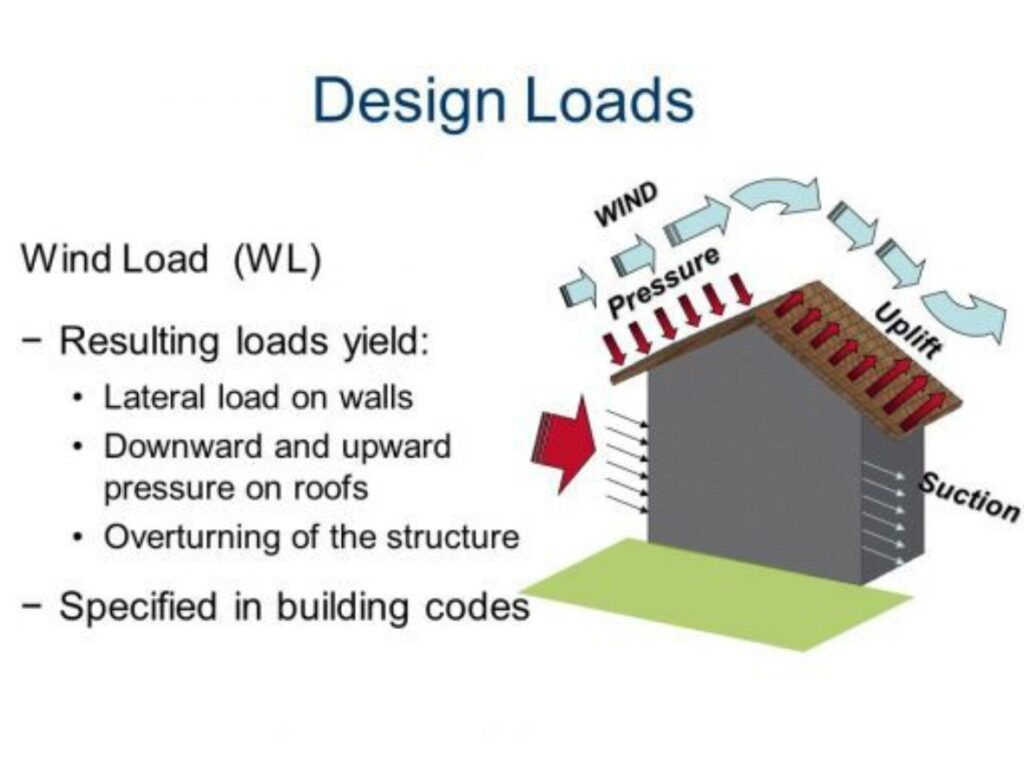
One of the most important things to consider during the initial concept design is the load paths. You need to ask yourself, “How will the lateral loads be transferred safely through the building to foundation levels?”
This is a concern for both lateral loads and vertical loads, which is why you need to consider elements such as floors, columns and vertical and horizontal bracing. A great example of this is illustrated in the Institution of Structural Engineers’ Stability of Buildings Part 1 and Part 2, which all engineers should have as a part of their engineering library.

Basic hand drawn sketches at the start of a project can give a clear idea of what needs to be achieved for the building to work structurally and so that other team members can accommodate these parameters. Horizontal stability systems use the horizontal plane and are required to transfer lateral forces to the vertical stability elements. Here are a few examples.
DIAPHRAGMS
Diaphragms are designed so that when building structures are subjected to lateral loadings such as earthquakes, the induced forces are transmitted through floor slabs and resisted by vertical structure components such as sheer walls and frames. We’ll talk more about these in upcoming articles.
Examples of diaphragms include concrete floors, profiled metal deck slabs and plywood sheets. Where profiled metal deck slabs or plywood sheets are acting as diaphragms, the engineer will need to specify the correct type and the number of fixings to transmit the required forces.
A key item that design engineers also need to be mindful of is the presence of any large openings placed in floor diaphragms and the effect they’ll have on the stability system.
TRIANGULATED BRACING
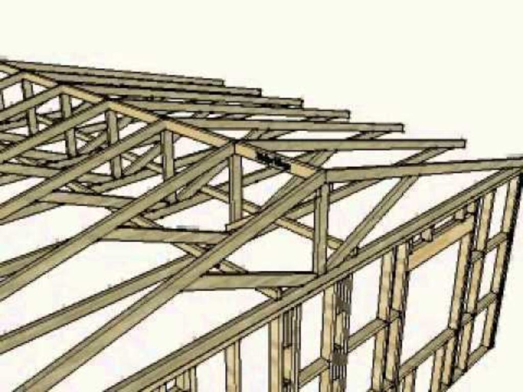
Warren or fink trusses are examples of this type of bracing. Modified versions of these are commonly used for lightweight structures, mainly in steel framed buildings. You’ve probably also seen the Warren Truss on bridge structures, even if you weren’t paying much attention.
These trusses use equilateral triangles to spread out the loads. One of the main advantages of a Warren Truss is its ability to spread the load evenly across a number of different members.
The Fink Truss usually offers economy in terms of steel weight for short-span, high-pitched roofs as the members are subdivided into shorter elements. There are a number of ways of arranging and subdividing the internal members. The Fink Truss is also commonly used to construct roofs in houses, providing a simple, adaptable and cost efficient roofing solution.

ABOUT LSY
Here at LSY, we’re used to dealing with horizontal stability systems and load paths. We’re working on numerous building structure projects throughout the UK and Ireland, and so if you’d like to discuss any project requirements of your own then please feel free to contact us. We’ll be more than happy to help!
Back to all news
